Computer Network Series
UNIT-1 COMPUTER NETWORK
What is a Computer Network?
o Computer Network is a group of computers connected with each other through wires, optical fiber or optical links so that various devices can interact with each other through a network.
o The aim of the computer network is the sharing of resources among various devices.
o In the case of computer network technology, there are several types of networks that vary from simple to complex level.
Components Of Computer Network:

Major components of a computer network are:
NIC(National interface card)
NIC is a device that helps the computer to communicate with another device. The network interface card contains the hardware addresses, the data-link layer protocol use this address to identify the system on the network so that it transfers the data to the correct destination.
There are two types of NIC: wireless NIC and wired NIC.
o Wireless NIC: All the modern laptops use the wireless NIC. In Wireless NIC, a connection is made using the antenna that employs the radio wave technology.
o Wired NIC: Cables use the wired NIC to transfer the data over the medium.
Hub
Hub is a central device that splits the network connection into multiple devices. When computer requests for information from a computer, it sends the request to the Hub. Hub distributes this request to all the interconnected computers.
Switches
Switch is a networking device that groups all the devices over the network to transfer the data to another device. A switch is better than Hub as it does not broadcast the message over the network, i.e., it sends the message to the device for which it belongs to. Therefore, we can say that switch sends the message directly from source to the destination.
Cables and connectors
Cable is a transmission media that transmits the communication signals. There are three types of cables:
o Twisted pair cable: It is a high-speed cable that transmits the data over 1Gbps or more.
o Coaxial cable: Coaxial cable resembles like a TV installation cable. Coaxial cable is more expensive than twisted pair cable, but it provides the high data transmission speed.
o Fibre optic cable: Fibre optic cable is a high-speed cable that transmits the data using light beams. It provides high data transmission speed as compared to other cables. It is more expensive as compared to other cables, so it is installed at the government level.
Router
Router is a device that connects the LAN to the internet. The router is mainly used to connect the distinct networks or connect the internet to multiple computers.
Modem
Modem connects the computer to the internet over the existing telephone line. A modem is not integrated with the computer motherboard. A modem is a separate part on the PC slot found on the motherboard.
Uses Of Computer Network
o Resource sharing: Resource sharing is the sharing of resources such as programs, printers, and data among the users on the network without the requirement of the physical location of the resource and user.
o Server-Client model: Computer networking is used in the server-client model. A server is a central computer used to store the information and maintained by the system administrator. Clients are the machines used to access the information stored in the server remotely.
o Communication medium: Computer network behaves as a communication medium among the users. For example, a company contains more than one computer has an email system which the employees use for daily communication.
o E-commerce: Computer network is also important in businesses. We can do the business over the internet. For example, amazon.com is doing their business over the internet, i.e., they are doing their business over the internet.
Features Of Computer network

A list Of Computer network features is given below.
o Communication speed
o File sharing
o Back up and Roll back is easy
o Software and Hardware sharing
o Security
o Scalability
o Reliability
Communication speed
Network provides us to communicate over the network in a fast and efficient manner. For example, we can do video conferencing, email messaging, etc. over the internet. Therefore, the computer network is a great way to share our knowledge and ideas.
File sharing
File sharing is one of the major advantage of the computer network. Computer network provides us to share the files with each other.
Back up and Roll back is easy
Since the files are stored in the main server which is centrally located. Therefore, it is easy to take the back up from the main server.
Software and Hardware sharing
We can install the applications on the main server, therefore, the user can access the applications centrally. So, we do not need to install the software on every machine. Similarly, hardware can also be shared.
Security
Network allows the security by ensuring that the user has the right to access the certain files and applications.
Scalability
Scalability means that we can add the new components on the network. Network must be scalable so that we can extend the network by adding new devices. But, it decreases the speed of the connection and data of the transmission speed also decreases, this increases the chances of error occurring. This problem can be overcome by using the routing or switching devices.
Reliability
Computer network can use the alternative source for the data communication in case of any hardware failure.
Computer Network Architecture
Computer Network Architecture is defined as the physical and logical design of the software, hardware, protocols, and media of the transmission of data. Simply we can say that how computers are organized and how tasks are allocated to the computer.
The two types of network architectures are used:
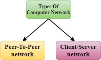
o Peer-To-Peer network
o Client/Server network
Peer-To-Peer network
o Peer-To-Peer network is a network in which all the computers are linked together with equal privilege and responsibilities for processing the data.
o Peer-To-Peer network is useful for small environments, usually up to 10 computers.
o Peer-To-Peer network has no dedicated server.
o Special permissions are assigned to each computer for sharing the resources, but this can lead to a problem if the computer with the resource is down.

Advantages Of Peer-To-Peer Network:
o It is less costly as it does not contain any dedicated server.
o If one computer stops working but, other computers will not stop working.
o It is easy to set up and maintain as each computer manages itself.
Disadvantages Of Peer-To-Peer Network:
o In the case of Peer-To-Peer network, it does not contain the centralized system . Therefore, it cannot back up the data as the data is different in different locations.
o It has a security issue as the device is managed itself.
Client/Server Network
o Client/Server network is a network model designed for the end users called clients, to access the resources such as songs, video, etc. from a central computer known as Server.
o The central controller is known as a server while all other computers in the network are called clients.
o A server performs all the major operations such as security and network management.
o A server is responsible for managing all the resources such as files, directories, printer, etc.
o All the clients communicate with each other through a server. For example, if client1 wants to send some data to client 2, then it first sends the request to the server for the permission. The server sends the response to the client 1 to initiate its communication with the client 2.

Advantages Of Client/Server network:
o A Client/Server network contains the centralized system. Therefore we can back up the data easily.
o A Client/Server network has a dedicated server that improves the overall performance of the whole system.
o Security is better in Client/Server network as a single server administers the shared resources.
o It also increases the speed of the sharing resources.
Disadvantages Of Client/Server network:
o Client/Server network is expensive as it requires the server with large memory.
o A server has a Network Operating System(NOS) to provide the resources to the clients, but the cost of NOS is very high.
o It requires a dedicated network administrator to manage all the resources.
Computer Network Components
Computer network components are the major parts which are needed to install the software. Some important network components are NIC, switch, cable, hub, router, and modem. Depending on the type of network that we need to install, some network components can also be removed. For example, the wireless network does not require a cable.
Following are the major components required to install a network:
NIC
o NIC stands for network interface card.
o NIC is a hardware component used to connect a computer with another computer onto a network
o It can support a transfer rate of 10,100 to 1000 Mb/s.
o The MAC address or physical address is encoded on the network card chip which is assigned by the IEEE to identify a network card uniquely. The MAC address is stored in the PROM (Programmable read-only memory).
There are two types of NIC:

1. Wired NIC
2. Wireless NIC
Wired NIC: The Wired NIC is present inside the motherboard. Cables and connectors are used with wired NIC to transfer data.
Wireless NIC: The wireless NIC contains the antenna to obtain the connection over the wireless network. For example, laptop computer contains the wireless NIC.
Hub
A Hub is a hardware device that divides the network connection among multiple devices. When computer requests for some information from a network, it first sends the request to the Hub through cable. Hub will broadcast this request to the entire network. All the devices will check whether the request belongs to them or not. If not, the request will be dropped.
The process used by the Hub consumes more bandwidth and limits the amount of communication. Nowadays, the use of hub is obsolete, and it is replaced by more advanced computer network components such as Switches, Routers.
Switch
A switch is a hardware device that connects multiple devices on a computer network. A Switch contains more advanced features than Hub. The Switch contains the updated table that decides where the data is transmitted or not. Switch delivers the message to the correct destination based on the physical address present in the incoming message. A Switch does not broadcast the message to the entire network like the Hub. It determines the device to whom the message is to be transmitted. Therefore, we can say that switch provides a direct connection between the source and destination. It increases the speed of the network.
Router
o A router is a hardware device which is used to connect a LAN with an internet connection. It is used to receive, analyze and forward the incoming packets to another network.
o A router works in a Layer 3 (Network layer) of the OSI Reference model.
o A router forwards the packet based on the information available in the routing table.
o It determines the best path from the available paths for the transmission of the packet.
Advantages Of Router:
o Security: The information which is transmitted to the network will traverse the entire cable, but the only specified device which has been addressed can read the data.
o Reliability: If the server has stopped functioning, the network goes down, but no other networks are affected that are served by the router.
o Performance: Router enhances the overall performance of the network. Suppose there are 24 workstations in a network generates a same amount of traffic. This increases the traffic load on the network. Router splits the single network into two networks of 12 workstations each, reduces the traffic load by half.
o Network range
Modem
o A modem is a hardware device that allows the computer to connect to the internet over the existing telephone line.
o A modem is not integrated with the motherboard rather than it is installed on the PCI slot found on the motherboard.
o It stands for Modulator/Demodulator. It converts the digital data into an analog signal over the telephone lines.
Based on the differences in speed and transmission rate, a modem can be classified in the following categories:
o Standard PC modem or Dial-up modem
o Cellular Modem
o Cable modem
Cables and Connectors
Cable is a transmission media used for transmitting a signal.
There are three types of cables used in transmission:
o Twisted pair cable
o Coaxial cable
o Fibre-optic cable
Computer Network Types
A computer network is a group of computers linked to each other that enables the computer to communicate with another computer and share their resources, data, and applications.
A computer network can be categorized by their size. A computer network is mainly of four types:

o LAN(Local Area Network)
o PAN(Personal Area Network)
o MAN(Metropolitan Area Network)
o WAN(Wide Area Network)
LAN(Local Area Network)
o Local Area Network is a group of computers connected to each other in a small area such as building, office.
o LAN is used for connecting two or more personal computers through a communication medium such as twisted pair, coaxial cable, etc.
o It is less costly as it is built with inexpensive hardware such as hubs, network adapters, and ethernet cables.
o The data is transferred at an extremely faster rate in Local Area Network.
o Local Area Network provides higher security.

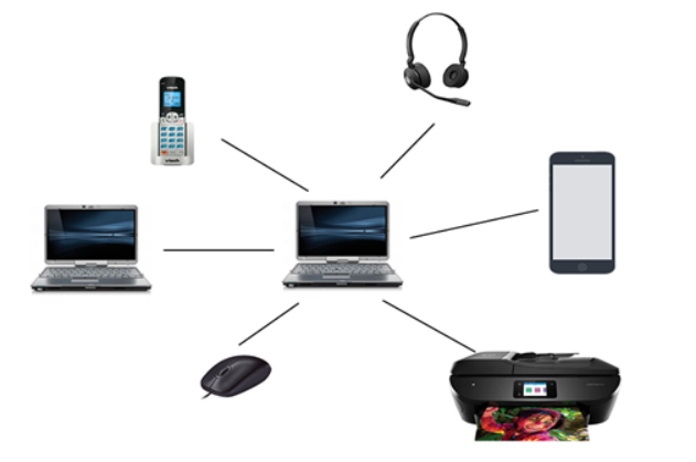
PAN(Personal Area Network)
o Personal Area Network is a network arranged within an individual person, typically within a range of 10 meters.
o Personal Area Network is used for connecting the computer devices of personal use is known as Personal Area Network.
o Thomas Zimmerman was the first research scientist to bring the idea of the Personal Area Network.
o Personal Area Network covers an area of 30 feet.
o Personal computer devices that are used to develop the personal area network are the laptop, mobile phones, media player and play stations.
There are two types of Personal Area Network:

o Wired Personal Area Network
o Wireless Personal Area Network
Wireless Personal Area Network: Wireless Personal Area Network is developed by simply using wireless technologies such as WiFi, Bluetooth. It is a low range network.
Play Video
Wired Personal Area Network: Wired Personal Area Network is created by using the USB.
Examples Of Personal Area Network:
o Body Area Network: Body Area Network is a network that moves with a person. For example, a mobile network moves with a person. Suppose a person establishes a network connection and then creates a connection with another device to share the information.
o Offline Network: An offline network can be created inside the home, so it is also known as a home network. A home network is designed to integrate the devices such as printers, computer, television but they are not connected to the internet.
o Small Home Office: It is used to connect a variety of devices to the internet and to a corporate network using a VPN
MAN(Metropolitan Area Network)
o A metropolitan area network is a network that covers a larger geographic area by interconnecting a different LAN to form a larger network.
o Government agencies use MAN to connect to the citizens and private industries.
o In MAN, various LANs are connected to each other through a telephone exchange line.
o The most widely used protocols in MAN are RS-232, Frame Relay, ATM, ISDN, OC-3, ADSL, etc.
o It has a higher range than Local Area Network(LAN).

Uses Of Metropolitan Area Network:
o MAN is used in communication between the banks in a city.
o It can be used in an Airline Reservation.
o It can be used in a college within a city.
o It can also be used for communication in the military.
WAN(Wide Area Network)
o A Wide Area Network is a network that extends over a large geographical area such as states or countries.
o A Wide Area Network is quite bigger network than the LAN.
o A Wide Area Network is not limited to a single location, but it spans over a large geographical area through a telephone line, fibre optic cable or satellite links.
o The internet is one of the biggest WAN in the world.
o A Wide Area Network is widely used in the field of Business, government, and education.

Examples Of Wide Area Network:
o Mobile Broadband: A 4G network is widely used across a region or country.
o Last mile: A telecom company is used to provide the internet services to the customers in hundreds of cities by connecting their home with fiber.
o Private network: A bank provides a private network that connects the 44 offices. This network is made by using the telephone leased line provided by the telecom company.
Advantages Of Wide Area Network:
Following are the advantages of the Wide Area Network:
o Geographical area: A Wide Area Network provides a large geographical area. Suppose if the branch of our office is in a different city then we can connect with them through WAN. The internet provides a leased line through which we can connect with another branch.
o Centralized data: In case of WAN network, data is centralized. Therefore, we do not need to buy the emails, files or back up servers.
o Get updated files: Software companies work on the live server. Therefore, the programmers get the updated files within seconds.
o Exchange messages: In a WAN network, messages are transmitted fast. The web application like Facebook, Whatsapp, Skype allows you to communicate with friends.
o Sharing of software and resources: In WAN network, we can share the software and other resources like a hard drive, RAM.
o Global business: We can do the business over the internet globally.
o High bandwidth: If we use the leased lines for our company then this gives the high bandwidth. The high bandwidth increases the data transfer rate which in turn increases the productivity of our company.
Disadvantages of Wide Area Network:
The following are the disadvantages of the Wide Area Network:
o Security issue: A WAN network has more security issues as compared to LAN and MAN network as all the technologies are combined together that creates the security problem.
o Needs Firewall & antivirus software: The data is transferred on the internet which can be changed or hacked by the hackers, so the firewall needs to be used. Some people can inject the virus in our system so antivirus is needed to protect from such a virus.
o High Setup cost: An installation cost of the WAN network is high as it involves the purchasing of routers, switches.
o Troubleshooting problems: It covers a large area so fixing the problem is difficult.
Internetwork
o An internetwork is defined as two or more computer network LANs or WAN or computer network segments are connected using devices, and they are configured by a local addressing scheme. This process is known as internetworking.
o An interconnection between public, private, commercial, industrial, or government computer networks can also be defined as internetworking.
o An internetworking uses the internet protocol.
o The reference model used for internetworking is Open System Interconnection(OSI).
Types Of Internetwork:
1. Extranet: An extranet is a communication network based on the internet protocol such as Transmission Control protocol and internet protocol. It is used for information sharing. The access to the extranet is restricted to only those users who have login credentials. An extranet is the lowest level of internetworking. It can be categorized as MAN, WAN or other computer networks. An extranet cannot have a single LAN, atleast it must have one connection to the external network.
2. Intranet: An intranet is a private network based on the internet protocol such as Transmission Control protocol and internet protocol. An intranet belongs to an organization which is only accessible by the organization's employee or members. The main aim of the intranet is to share the information and resources among the organization employees. An intranet provides the facility to work in groups and for teleconferences.
Intranet advantages:
o Communication: It provides a cheap and easy communication. An employee of the organization can communicate with another employee through email, chat.
o Time-saving: Information on the intranet is shared in real time, so it is time-saving.
o Collaboration: Collaboration is one of the most important advantage of the intranet. The information is distributed among the employees of the organization and can only be accessed by the authorized user.
o Platform independency: It is a neutral architecture as the computer can be connected to another device with different architecture.
o Cost effective: People can see the data and documents by using the browser and distributes the duplicate copies over the intranet. This leads to a reduction in the cost.
What is Network Topology?
Topology defines the structure of the network of how all the components are interconnected to each other. There are two types of topology: physical and logical topology.
Types of Network Topology
Physical topology is the geometric representation of all the nodes in a network. There are six types of network topology which are Bus Topology, Ring Topology, Tree Topology, Star Topology, Mesh Topology, and Hybrid Topology.

1) Bus Topology

o The bus topology is designed in such a way that all the stations are connected through a single cable known as a backbone cable.
o Each node is either connected to the backbone cable by drop cable or directly connected to the backbone cable.
o When a node wants to send a message over the network, it puts a message over the network. All the stations available in the network will receive the message whether it has been addressed or not.
o The bus topology is mainly used in 802.3 (ethernet) and 802.4 standard networks.
o The configuration of a bus topology is quite simpler as compared to other topologies.
o The backbone cable is considered as a "single lane" through which the message is broadcast to all the stations.
o The most common access method of the bus topologies is CSMA (Carrier Sense Multiple Access).
CSMA: It is a media access control used to control the data flow so that data integrity is maintained, i.e., the packets do not get lost. There are two alternative ways of handling the problems that occur when two nodes send the messages simultaneously.
o CSMA CD: CSMA CD (Collision detection) is an access method used to detect the collision. Once the collision is detected, the sender will stop transmitting the data. Therefore, it works on "recovery after the collision".
o CSMA CA: CSMA CA (Collision Avoidance) is an access method used to avoid the collision by checking whether the transmission media is busy or not. If busy, then the sender waits until the media becomes idle. This technique effectively reduces the possibility of the collision. It does not work on "recovery after the collision".
Advantages of Bus topology:
o Low-cost cable: In bus topology, nodes are directly connected to the cable without passing through a hub. Therefore, the initial cost of installation is low.
o Moderate data speeds: Coaxial or twisted pair cables are mainly used in bus-based networks that support upto 10 Mbps.
o Familiar technology: Bus topology is a familiar technology as the installation and troubleshooting techniques are well known, and hardware components are easily available.
o Limited failure: A failure in one node will not have any effect on other nodes.
Disadvantages of Bus topology:
o Extensive cabling: A bus topology is quite simpler, but still it requires a lot of cabling.
o Difficult troubleshooting: It requires specialized test equipment to determine the cable faults. If any fault occurs in the cable, then it would disrupt the communication for all the nodes.
o Signal interference: If two nodes send the messages simultaneously, then the signals of both the nodes collide with each other.
o Reconfiguration difficult: Adding new devices to the network would slow down the network.
o Attenuation: Attenuation is a loss of signal leads to communication issues. Repeaters are used to regenerate the signal.
2) Ring Topology
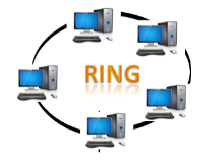
o Ring topology is like a bus topology, but with connected ends.
o The node that receives the message from the previous computer will retransmit to the next node.
o The data flows in one direction, i.e., it is unidirectional.
o The data flows in a single loop continuously known as an endless loop.
o It has no terminated ends, i.e., each node is connected to other node and having no termination point.
o The data in a ring topology flow in a clockwise direction.
o The most common access method of the ring topology is token passing.
o Token passing: It is a network access method in which token is passed from one node to another node.
o Token: It is a frame that circulates around the network.
Working of Token passing
o A token moves around the network, and it is passed from computer to computer until it reaches the destination.
o The sender modifies the token by putting the address along with the data.
o The data is passed from one device to another device until the destination address matches. Once the token received by the destination device, then it sends the acknowledgment to the sender.
o In a ring topology, a token is used as a carrier.
Advantages of Ring topology:
o Network Management: Faulty devices can be removed from the network without bringing the network down.
o Product availability: Many hardware and software tools for network operation and monitoring are available.
o Cost: Twisted pair cabling is inexpensive and easily available. Therefore, the installation cost is very low.
o Reliable: It is a more reliable network because the communication system is not dependent on the single host computer.
Disadvantages of Ring topology:
o Difficult troubleshooting: It requires specialized test equipment to determine the cable faults. If any fault occurs in the cable, then it would disrupt the communication for all the nodes.
o Failure: The breakdown in one station leads to the failure of the overall network.
o Reconfiguration difficult: Adding new devices to the network would slow down the network.
o Delay: Communication delay is directly proportional to the number of nodes. Adding new devices increases the communication delay.
3) Star Topology
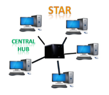
o Star topology is an arrangement of the network in which every node is connected to the central hub, switch or a central computer.
o The central computer is known as a server, and the peripheral devices attached to the server are known as clients.
o Coaxial cable or RJ-45 cables are used to connect the computers.
o Hubs or Switches are mainly used as connection devices in a physical star topology.
o Star topology is the most popular topology in network implementation.
Advantages of Star topology
o Efficient troubleshooting: Troubleshooting is quite efficient in a star topology as compared to bus topology. In a bus topology, the manager has to inspect the kilometers of cable. In a star topology, all the stations are connected to the centralized network. Therefore, the network administrator has to go to the single station to troubleshoot the problem.
o Network control: Complex network control features can be easily implemented in the star topology. Any changes made in the star topology are automatically accommodated.
o Limited failure: As each station is connected to the central hub with its own cable, therefore failure in one cable will not affect the entire network.
o Familiar technology: Star topology is a familiar technology as its tools are cost-effective.
o Easily expandable: It is easily expandable as new stations can be added to the open ports on the hub.
o Cost effective: Star topology networks are cost-effective as it uses inexpensive coaxial cable.
o High data speeds: It supports a bandwidth of approx 100Mbps. Ethernet 100BaseT is one of the most popular Star topology networks.
Disadvantages of Star topology
o A Central point of failure: If the central hub or switch goes down, then all the connected nodes will not be able to communicate with each other.
o Cable: Sometimes cable routing becomes difficult when a significant amount of routing is required.
4) Tree topology

o Tree topology combines the characteristics of bus topology and star topology.
o A tree topology is a type of structure in which all the computers are connected with each other in hierarchical fashion.
o The top-most node in tree topology is known as a root node, and all other nodes are the descendants of the root node.
o There is only one path exists between two nodes for the data transmission. Thus, it forms a parent-child hierarchy.
Advantages of Tree topology
o Support for broadband transmission: Tree topology is mainly used to provide broadband transmission, i.e., signals are sent over long distances without being attenuated.
o Easily expandable: We can add the new device to the existing network. Therefore, we can say that tree topology is easily expandable.
o Easily manageable: In tree topology, the whole network is divided into segments known as star networks which can be easily managed and maintained.
o Error detection: Error detection and error correction are very easy in a tree topology.
o Limited failure: The breakdown in one station does not affect the entire network.
o Point-to-point wiring: It has point-to-point wiring for individual segments.
Disadvantages of Tree topology
o Difficult troubleshooting: If any fault occurs in the node, then it becomes difficult to troubleshoot the problem.
o High cost: Devices required for broadband transmission are very costly.
o Failure: A tree topology mainly relies on main bus cable and failure in main bus cable will damage the overall network.
o Reconfiguration difficult: If new devices are added, then it becomes difficult to reconfigure.
5) Mesh topology
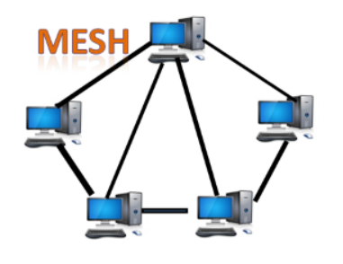
o Mesh technology is an arrangement of the network in which computers are interconnected with each other through various redundant connections.
o There are multiple paths from one computer to another computer.
o It does not contain the switch, hub or any central computer which acts as a central point of communication.
o The Internet is an example of the mesh topology.
o Mesh topology is mainly used for WAN implementations where communication failures are a critical concern.
o Mesh topology is mainly used for wireless networks.
o Mesh topology can be formed by using the formula:
Number of cables = (n*(n-1))/2;
Where n is the number of nodes that represents the network.
Play Video
Mesh topology is divided into two categories:
o Fully connected mesh topology
o Partially connected mesh topology

o Full Mesh Topology: In a full mesh topology, each computer is connected to all the computers available in the network.
o Partial Mesh Topology: In a partial mesh topology, not all but certain computers are connected to those computers with which they communicate frequently.
Advantages of Mesh topology:
Reliable: The mesh topology networks are very reliable as if any link breakdown will not affect the communication between connected computers.
Fast Communication: Communication is very fast between the nodes.
Easier Reconfiguration: Adding new devices would not disrupt the communication between other devices.
Disadvantages of Mesh topology
o Cost: A mesh topology contains a large number of connected devices such as a router and more transmission media than other topologies.
o Management: Mesh topology networks are very large and very difficult to maintain and manage. If the network is not monitored carefully, then the communication link failure goes undetected.
o Efficiency: In this topology, redundant connections are high that reduces the efficiency of the network.
6) Hybrid Topology

o The combination of various different topologies is known as Hybrid topology.
o A Hybrid topology is a connection between different links and nodes to transfer the data.
o When two or more different topologies are combined together is termed as Hybrid topology and if similar topologies are connected with each other will not result in Hybrid topology. For example, if there exist a ring topology in one branch of ICICI bank and bus topology in another branch of ICICI bank, connecting these two topologies will result in Hybrid topology.
Advantages of Hybrid Topology
o Reliable: If a fault occurs in any part of the network will not affect the functioning of the rest of the network.
o Scalable: Size of the network can be easily expanded by adding new devices without affecting the functionality of the existing network.
o Flexible: This topology is very flexible as it can be designed according to the requirements of the organization.
o Effective: Hybrid topology is very effective as it can be designed in such a way that the strength of the network is maximized and weakness of the network is minimized.
Disadvantages of Hybrid topology
o Complex design: The major drawback of the Hybrid topology is the design of the Hybrid network. It is very difficult to design the architecture of the Hybrid network.
o Costly Hub: The Hubs used in the Hybrid topology are very expensive as these hubs are different from usual Hubs used in other topologies.
o Costly infrastructure: The infrastructure cost is very high as a hybrid network requires a lot of cabling, network devices, etc.
Transmission modes
o The way in which data is transmitted from one device to another device is known as transmission mode.
o The transmission mode is also known as the communication mode.
o Each communication channel has a direction associated with it, and transmission media provide the direction. Therefore, the transmission mode is also known as a directional mode.
o The transmission mode is defined in the physical layer.
The Transmission mode is divided into three categories:
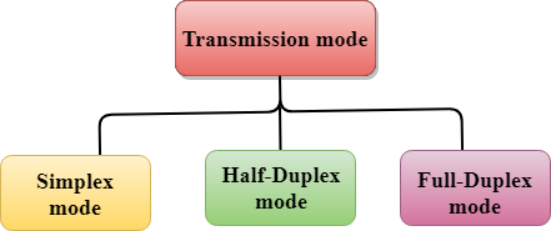
o Simplex mode
o Half-duplex mode
o Full-duplex mode
Simplex mode

o In Simplex mode, the communication is unidirectional, i.e., the data flow in one direction.
o A device can only send the data but cannot receive it or it can receive the data but cannot send the data.
o This transmission mode is not very popular as mainly communications require the two-way exchange of data. The simplex mode is used in the business field as in sales that do not require any corresponding reply.
o The radio station is a simplex channel as it transmits the signal to the listeners but never allows them to transmit back.
o Keyboard and Monitor are the examples of the simplex mode as a keyboard can only accept the data from the user and monitor can only be used to display the data on the screen.
o The main advantage of the simplex mode is that the full capacity of the communication channel can be utilized during transmission.
Advantage of Simplex mode:
o In simplex mode, the station can utilize the entire bandwidth of the communication channel, so that more data can be transmitted at a time.
Disadvantage of Simplex mode:
o Communication is unidirectional, so it has no inter-communication between devices.
Half-Duplex mode

o In a Half-duplex channel, direction can be reversed, i.e., the station can transmit and receive the data as well.
o Messages flow in both the directions, but not at the same time.
o The entire bandwidth of the communication channel is utilized in one direction at a time.
o In half-duplex mode, it is possible to perform the error detection, and if any error occurs, then the receiver requests the sender to retransmit the data.
o A Walkie-talkie is an example of the Half-duplex mode. In Walkie-talkie, one party speaks, and another party listens. After a pause, the other speaks and first party listens. Speaking simultaneously will create the distorted sound which cannot be understood.
Advantage of Half-duplex mode:
o In half-duplex mode, both the devices can send and receive the data and also can utilize the entire bandwidth of the communication channel during the transmission of data.
Disadvantage of Half-Duplex mode:
o In half-duplex mode, when one device is sending the data, then another has to wait, this causes the delay in sending the data at the right time.
Full-duplex mode

o In Full duplex mode, the communication is bi-directional, i.e., the data flow in both the directions.
o Both the stations can send and receive the message simultaneously.
o Full-duplex mode has two simplex channels. One channel has traffic moving in one direction, and another channel has traffic flowing in the opposite direction.
o The Full-duplex mode is the fastest mode of communication between devices.
o The most common example of the full-duplex mode is a telephone network. When two people are communicating with each other by a telephone line, both can talk and listen at the same time.
Advantage of Full-duplex mode:
o Both the stations can send and receive the data at the same time.
Disadvantage of Full-duplex mode:
o If there is no dedicated path exists between the devices, then the capacity of the communication channel is divided into two parts.
OSI MODEL
OSI stands for Open Systems Interconnection. It has been developed by ISO – ‘International Organization for Standardization‘, in the year 1984. It is a 7 layer architecture with each layer having specific functionality to perform. All these 7 layers work collaboratively to transmit the data from one person to another across the globe.

1. Physical Layer (Layer 1) :
The lowest layer of the OSI reference model is the physical layer. It is responsible for the actual physical connection between the devices. The physical layer contains information in the form of bits. It is responsible for transmitting individual bits from one node to the next. When receiving data, this layer will get the signal received and convert it into 0s and 1s and send them to the Data Link layer, which will put the frame back together.

The functions of the physical layer are as follows:
1. Bit synchronization: The physical layer provides the synchronization of the bits by providing a clock. This clock controls both sender and receiver thus providing synchronization at bit level.
2. Bit rate control: The Physical layer also defines the transmission rate i.e. the number of bits sent per second.
3. Physical topologies: Physical layer specifies the way in which the different, devices/nodes are arranged in a network i.e. bus, star, or mesh topology.
4. Transmission mode: Physical layer also defines the way in which the data flows between the two connected devices. The various transmission modes possible are Simplex, half-duplex and full-duplex.
* Hub, Repeater, Modem, Cables are Physical Layer devices.
** Network Layer, Data Link Layer, and Physical Layer are also known as Lower Layers or Hardware Layers.
2. Data Link Layer (DLL) (Layer 2) :
The data link layer is responsible for the node-to-node delivery of the message. The main function of this layer is to make sure data transfer is error-free from one node to another, over the physical layer. When a packet arrives in a network, it is the responsibility of DLL to transmit it to the Host using its MAC address.
Data Link Layer is divided into two sublayers:
1. Logical Link Control (LLC)
2. Media Access Control (MAC)
The packet received from the Network layer is further divided into frames depending on the frame size of NIC(Network Interface Card). DLL also encapsulates Sender and Receiver’s MAC address in the header.
The Receiver’s MAC address is obtained by placing an ARP(Address Resolution Protocol) request onto the wire asking “Who has that IP address?” and the destination host will reply with its MAC address.

The functions of the Data Link layer are :
1. Framing: Framing is a function of the data link layer. It provides a way for a sender to transmit a set of bits that are meaningful to the receiver. This can be accomplished by attaching special bit patterns to the beginning and end of the frame.
2. Physical addressing: After creating frames, the Data link layer adds physical addresses (MAC address) of the sender and/or receiver in the header of each frame.
3. Error control: Data link layer provides the mechanism of error control in which it detects and retransmits damaged or lost frames.
4. Flow Control: The data rate must be constant on both sides else the data may get corrupted thus, flow control coordinates the amount of data that can be sent before receiving acknowledgement.
5. Access control: When a single communication channel is shared by multiple devices, the MAC sub-layer of the data link layer helps to determine which device has control over the channel at a given time.
* Packet in Data Link layer is referred to as Frame.
** Data Link layer is handled by the NIC (Network Interface Card) and device drivers of host machines.
*** Switch & Bridge are Data Link Layer devices.
3. Network Layer (Layer 3) :
The network layer works for the transmission of data from one host to the other located in different networks. It also takes care of packet routing i.e. selection of the shortest path to transmit the packet, from the number of routes available. The sender & receiver’s IP addresses are placed in the header by the network layer.
The functions of the Network layer are :
1. Routing: The network layer protocols determine which route is suitable from source to destination. This function of the network layer is known as routing.
2. Logical Addressing: In order to identify each device on internetwork uniquely, the network layer defines an addressing scheme. The sender & receiver’s IP addresses are placed in the header by the network layer. Such an address distinguishes each device uniquely and universally.
* Segment in Network layer is referred to as Packet.

** Network layer is implemented by networking devices such as routers.
4. Transport Layer (Layer 4) :
The transport layer provides services to the application layer and takes services from the network layer. The data in the transport layer is referred to as Segments. It is responsible for the End to End Delivery of the complete message. The transport layer also provides the acknowledgement of the successful data transmission and re-transmits the data if an error is found.
At sender’s side: Transport layer receives the formatted data from the upper layers, performs Segmentation, and also implements Flow & Error control to ensure proper data transmission. It also adds Source and Destination port numbers in its header and forwards the segmented data to the Network Layer.
Note: The sender needs to know the port number associated with the receiver’s application.
Generally, this destination port number is configured, either by default or manually. For example, when a web application makes a request to a web server, it typically uses port number 80, because this is the default port assigned to web applications. Many applications have default ports assigned.
At receiver’s side: Transport Layer reads the port number from its header and forwards the Data which it has received to the respective application. It also performs sequencing and reassembling of the segmented data.
The functions of the transport layer are as follows:
1. Segmentation and Reassembly: This layer accepts the message from the (session) layer, and breaks the message into smaller units. Each of the segments produced has a header associated with it. The transport layer at the destination station reassembles the message.
2. Service Point Addressing: In order to deliver the message to the correct process, the transport layer header includes a type of address called service point address or port address. Thus by specifying this address, the transport layer makes sure that the message is delivered to the correct process.
The services provided by the transport layer :
A. Connection-Oriented Service: It is a three-phase process that includes
– Connection Establishment
– Data Transfer
– Termination / disconnection
In this type of transmission, the receiving device sends an acknowledgement, back to the source after a packet or group of packets is received. This type of transmission is reliable and secure.
B. Connectionless service: It is a one-phase process and includes Data Transfer. In this type of transmission, the receiver does not acknowledge receipt of a packet. This approach allows for much faster communication between devices. Connection-oriented service is more reliable than connectionless Service.
* Data in the Transport Layer is called as Segments.
** Transport layer is operated by the Operating System. It is a part of the OS and communicates with the Application Layer by making system calls.
Transport Layer is called as Heart of OSI model.
5. Session Layer (Layer 5) :
This layer is responsible for the establishment of connection, maintenance of sessions, authentication, and also ensures security.
The functions of the session layer are :
1. Session establishment, maintenance, and termination: The layer allows the two processes to establish, use and terminate a connection.
2. Synchronization: This layer allows a process to add checkpoints which are considered synchronization points into the data. These synchronization points help to identify the error so that the data is re-synchronized properly, and ends of the messages are not cut prematurely and data loss is avoided.
3. Dialog Controller: The session layer allows two systems to start communication with each other in half-duplex or full-duplex.
**All the below 3 layers(including Session Layer) are integrated as a single layer in the TCP/IP model as “Application Layer”.
**Implementation of these 3 layers is done by the network application itself. These are also known as Upper Layers or Software Layers.
Scenario:
Let us consider a scenario where a user wants to send a message through some Messenger application running in his browser. The “Messenger” here acts as the application layer which provides the user with an interface to create the data. This message or so-called Data is compressed, encrypted (if any secure data), and converted into bits (0’s and 1’s) so that it can be transmitted.

6. Presentation Layer (Layer 6):
The presentation layer is also called the Translation layer. The data from the application layer is extracted here and manipulated as per the required format to transmit over the network.
The functions of the presentation layer are :
· Translation: For example, ASCII to EBCDIC.
· Encryption/ Decryption: Data encryption translates the data into another form or code. The encrypted data is known as the ciphertext and the decrypted data is known as plain text. A key value is used for encrypting as well as decrypting data.
· Compression: Reduces the number of bits that need to be transmitted on the network.
7. Application Layer (Layer 7) :
At the very top of the OSI Reference Model stack of layers, we find the Application layer which is implemented by the network applications. These applications produce the data, which has to be transferred over the network. This layer also serves as a window for the application services to access the network and for displaying the received information to the user.
Example: Application – Browsers, Skype Messenger, etc.
**Application Layer is also called Desktop Layer.

The functions of the Application layer are :
1. Network Virtual Terminal
2. FTAM-File transfer access and management
3. Mail Services
4. Directory Services
TCP/IP model
o The TCP/IP model was developed prior to the OSI model.
o The TCP/IP model is not exactly similar to the OSI model.
o The TCP/IP model consists of five layers: the application layer, transport layer, network layer, data link layer and physical layer.
o The first four layers provide physical standards, network interface, internetworking, and transport functions that correspond to the first four layers of the OSI model and these four layers are represented in TCP/IP model by a single layer called the application layer.
o TCP/IP is a hierarchical protocol made up of interactive modules, and each of them provides specific functionality.
Here, hierarchical means that each upper-layer protocol is supported by two or more lower-level protocols.
Functions of TCP/IP layers:

Network Access Layer
o A network layer is the lowest layer of the TCP/IP model.
o A network layer is the combination of the Physical layer and Data Link layer defined in the OSI reference model.
o It defines how the data should be sent physically through the network.
o This layer is mainly responsible for the transmission of the data between two devices on the same network.
o The functions carried out by this layer are encapsulating the IP datagram into frames transmitted by the network and mapping of IP addresses into physical addresses.
o The protocols used by this layer are ethernet, token ring, FDDI, X.25, frame relay.
Internet Layer
o An internet layer is the second layer of the TCP/IP model.
o An internet layer is also known as the network layer.
o The main responsibility of the internet layer is to send the packets from any network, and they arrive at the destination irrespective of the route they take.
Following are the protocols used in this layer are:
IP Protocol: IP protocol is used in this layer, and it is the most significant part of the entire TCP/IP suite.
Following are the responsibilities of this protocol:
o IP Addressing: This protocol implements logical host addresses known as IP addresses. The IP addresses are used by the internet and higher layers to identify the device and to provide internetwork routing.
o Host-to-host communication: It determines the path through which the data is to be transmitted.
o Data Encapsulation and Formatting: An IP protocol accepts the data from the transport layer protocol. An IP protocol ensures that the data is sent and received securely, it encapsulates the data into message known as IP datagram.
o Fragmentation and Reassembly: The limit imposed on the size of the IP datagram by data link layer protocol is known as Maximum Transmission unit (MTU). If the size of IP datagram is greater than the MTU unit, then the IP protocol splits the datagram into smaller units so that they can travel over the local network. Fragmentation can be done by the sender or intermediate router. At the receiver side, all the fragments are reassembled to form an original message.
o Routing: When IP datagram is sent over the same local network such as LAN, MAN, WAN, it is known as direct delivery. When source and destination are on the distant network, then the IP datagram is sent indirectly. This can be accomplished by routing the IP datagram through various devices such as routers.
ARP Protocol
o ARP stands for Address Resolution Protocol.
o ARP is a network layer protocol which is used to find the physical address from the IP address.
o The two terms are mainly associated with the ARP Protocol:
o ARP request: When a sender wants to know the physical address of the device, it broadcasts the ARP request to the network.
o ARP reply: Every device attached to the network will accept the ARP request and process the request, but only recipient recognize the IP address and sends back its physical address in the form of ARP reply. The recipient adds the physical address both to its cache memory and to the datagram header
ICMP Protocol
o ICMP stands for Internet Control Message Protocol.
o It is a mechanism used by the hosts or routers to send notifications regarding datagram problems back to the sender.
o A datagram travels from router-to-router until it reaches its destination. If a router is unable to route the data because of some unusual conditions such as disabled links, a device is on fire or network congestion, then the ICMP protocol is used to inform the sender that the datagram is undeliverable.
o An ICMP protocol mainly uses two terms:
o ICMP Test: ICMP Test is used to test whether the destination is reachable or not.
o ICMP Reply: ICMP Reply is used to check whether the destination device is responding or not.
o The core responsibility of the ICMP protocol is to report the problems, not correct them. The responsibility of the correction lies with the sender.
o ICMP can send the messages only to the source, but not to the intermediate routers because the IP datagram carries the addresses of the source and destination but not of the router that it is passed to.
Transport Layer
The transport layer is responsible for the reliability, flow control, and correction of data which is being sent over the network.
The two protocols used in the transport layer are User Datagram protocol and Transmission control protocol.
o User Datagram Protocol (UDP)
o It provides connectionless service and end-to-end delivery of transmission.
o It is an unreliable protocol as it discovers the errors but not specify the error.
o User Datagram Protocol discovers the error, and ICMP protocol reports the error to the sender that user datagram has been damaged.
o UDP consists of the following fields:
Source port address: The source port address is the address of the application program that has created the message.
Destination port address: The destination port address is the address of the application program that receives the message.
Total length: It defines the total number of bytes of the user datagram in bytes.
Checksum: The checksum is a 16-bit field used in error detection.
o UDP does not specify which packet is lost. UDP contains only checksum; it does not contain any ID of a data segment.


o Transmission Control Protocol (TCP)
o It provides a full transport layer services to applications.
o It creates a virtual circuit between the sender and receiver, and it is active for the duration of the transmission.
o TCP is a reliable protocol as it detects the error and retransmits the damaged frames. Therefore, it ensures all the segments must be received and acknowledged before the transmission is considered to be completed and a virtual circuit is discarded.
o At the sending end, TCP divides the whole message into smaller units known as segment, and each segment contains a sequence number which is required for reordering the frames to form an original message.
o At the receiving end, TCP collects all the segments and reorders them based on sequence numbers.
Application Layer
o An application layer is the topmost layer in the TCP/IP model.
o It is responsible for handling high-level protocols, issues of representation.
o This layer allows the user to interact with the application.
o When one application layer protocol wants to communicate with another application layer, it forwards its data to the transport layer.
o There is an ambiguity occurs in the application layer. Every application cannot be placed inside the application layer except those who interact with the communication system. For example: text editor cannot be considered in application layer while web browser using HTTP protocol to interact with the network where HTTP protocol is an application layer protocol.
Following are the main protocols used in the application layer:
o HTTP: HTTP stands for Hypertext transfer protocol. This protocol allows us to access the data over the world wide web. It transfers the data in the form of plain text, audio, video. It is known as a Hypertext transfer protocol as it has the efficiency to use in a hypertext environment where there are rapid jumps from one document to another.
o SNMP: SNMP stands for Simple Network Management Protocol. It is a framework used for managing the devices on the internet by using the TCP/IP protocol suite.
o SMTP: SMTP stands for Simple mail transfer protocol. The TCP/IP protocol that supports the e-mail is known as a Simple mail transfer protocol. This protocol is used to send the data to another e-mail address.
o DNS: DNS stands for Domain Name System. An IP address is used to identify the connection of a host to the internet uniquely. But, people prefer to use the names instead of addresses. Therefore, the system that maps the name to the address is known as Domain Name System.
o TELNET: It is an abbreviation for Terminal Network. It establishes the connection between the local computer and remote computer in such a way that the local terminal appears to be a terminal at the remote system.
o FTP: FTP stands for File Transfer Protocol. FTP is a standard internet protocol used for transmitting the files from one computer to another computer.
Switching techniques
In large networks, there can be multiple paths from sender to receiver. The switching technique will decide the best route for data transmission.
Switching technique is used to connect the systems for making one-to-one communication.
Classification Of Switching Techniques
![]()
Circuit Switching
o Circuit switching is a switching technique that establishes a dedicated path between sender and receiver.
o In the Circuit Switching Technique, once the connection is established then the dedicated path will remain to exist until the connection is terminated.
o Circuit switching in a network operates in a similar way as the telephone works.
o A complete end-to-end path must exist before the communication takes place.
o In case of circuit switching technique, when any user wants to send the data, voice, video, a request signal is sent to the receiver then the receiver sends back the acknowledgment to ensure the availability of the dedicated path. After receiving the acknowledgment, dedicated path transfers the data.
o Circuit switching is used in public telephone network. It is used for voice transmission.
o Fixed data can be transferred at a time in circuit switching technology.
Communication through circuit switching has 3 phases:
o Circuit establishment
o Data transfer
o Circuit Disconnect

Circuit Switching can use either of the two technologies:
Space Division Switches:
o Space Division Switching is a circuit switching technology in which a single transmission path is accomplished in a switch by using a physically separate set of crosspoints.
o Space Division Switching can be achieved by using crossbar switch. A crossbar switch is a metallic crosspoint or semiconductor gate that can be enabled or disabled by a control unit.
o The Crossbar switch is made by using the semiconductor. For example, Xilinx crossbar switch using FPGAs.
o Space Division Switching has high speed, high capacity, and nonblocking switches.
Space Division Switches can be categorized in two ways:
o Crossbar Switch
o Multistage Switch
Crossbar Switch
The Crossbar switch is a switch that has n input lines and n output lines. The crossbar switch has n2 intersection points known as crosspoints.
Disadvantage of Crossbar switch:
The number of crosspoints increases as the number of stations is increased. Therefore, it becomes very expensive for a large switch. The solution to this is to use a multistage switch.
Multistage Switch
o Multistage Switch is made by splitting the crossbar switch into the smaller units and then interconnecting them.
o It reduces the number of crosspoints.
o If one path fails, then there will be an availability of another path.
Advantages Of Circuit Switching:
o In the case of Circuit Switching technique, the communication channel is dedicated.
o It has fixed bandwidth.
Disadvantages Of Circuit Switching:
o Once the dedicated path is established, the only delay occurs in the speed of data transmission.
o It takes a long time to establish a connection approx 10 seconds during which no data can be transmitted.
o It is more expensive than other switching techniques as a dedicated path is required for each connection.
o It is inefficient to use because once the path is established and no data is transferred, then the capacity of the path is wasted.
o In this case, the connection is dedicated therefore no other data can be transferred even if the channel is free.
Message Switching
o Message Switching is a switching technique in which a message is transferred as a complete unit and routed through intermediate nodes at which it is stored and forwarded.
o In Message Switching technique, there is no establishment of a dedicated path between the sender and receiver.
o The destination address is appended to the message. Message Switching provides a dynamic routing as the message is routed through the intermediate nodes based on the information available in the message.
o Message switches are programmed in such a way so that they can provide the most efficient routes.
o Each and every node stores the entire message and then forward it to the next node. This type of network is known as store and forward network.
o Message switching treats each message as an independent entity.

Advantages Of Message Switching
o Data channels are shared among the communicating devices that improve the efficiency of using available bandwidth.
o Traffic congestion can be reduced because the message is temporarily stored in the nodes.
o Message priority can be used to manage the network.
o The size of the message which is sent over the network can be varied. Therefore, it supports the data of unlimited size.
Disadvantages Of Message Switching
o The message switches must be equipped with sufficient storage to enable them to store the messages until the message is forwarded.
o The Long delay can occur due to the storing and forwarding facility provided by the message switching technique.
Packet Switching
o The packet switching is a switching technique in which the message is sent in one go, but it is divided into smaller pieces, and they are sent individually.
o The message splits into smaller pieces known as packets and packets are given a unique number to identify their order at the receiving end.
o Every packet contains some information in its headers such as source address, destination address and sequence number.
o Packets will travel across the network, taking the shortest path as possible.
o All the packets are reassembled at the receiving end in correct order.
o If any packet is missing or corrupted, then the message will be sent to resend the message.
o If the correct order of the packets is reached, then the acknowledgment message will be sent.

Approaches Of Packet Switching:
There are two approaches to Packet Switching:
Datagram Packet switching:
o It is a packet switching technology in which packet is known as a datagram, is considered as an independent entity. Each packet contains the information about the destination and switch uses this information to forward the packet to the correct destination.
o The packets are reassembled at the receiving end in correct order.
o In Datagram Packet Switching technique, the path is not fixed.
o Intermediate nodes take the routing decisions to forward the packets.
o Datagram Packet Switching is also known as connectionless switching.
Virtual Circuit Switching
o Virtual Circuit Switching is also known as connection-oriented switching.
o In the case of Virtual circuit switching, a preplanned route is established before the messages are sent.
o Call request and call accept packets are used to establish the connection between sender and receiver.
o In this case, the path is fixed for the duration of a logical connection.
Let's understand the concept of virtual circuit switching through a diagram:

o In the above diagram, A and B are the sender and receiver respectively. 1 and 2 are the nodes.
o Call request and call accept packets are used to establish a connection between the sender and receiver.
o When a route is established, data will be transferred.
o After transmission of data, an acknowledgment signal is sent by the receiver that the message has been received.
o If the user wants to terminate the connection, a clear signal is sent for the termination.
Differences b/w Datagram approach and Virtual Circuit approach
Datagram approach | Virtual Circuit approach |
Node takes routing decisions to forward the packets. | Node does not take any routing decision. |
Congestion cannot occur as all the packets travel in different directions. | Congestion can occur when the node is busy, and it does not allow other packets to pass through. |
It is more flexible as all the packets are treated as an independent entity. | It is not very flexible. |
Advantages Of Packet Switching:
o Cost-effective: In packet switching technique, switching devices do not require massive secondary storage to store the packets, so cost is minimized to some extent. Therefore, we can say that the packet switching technique is a cost-effective technique.
o Reliable: If any node is busy, then the packets can be rerouted. This ensures that the Packet Switching technique provides reliable communication.
o Efficient: Packet Switching is an efficient technique. It does not require any established path prior to the transmission, and many users can use the same communication channel simultaneously, hence makes use of available bandwidth very efficiently.
Disadvantages Of Packet Switching:
o Packet Switching technique cannot be implemented in those applications that require low delay and high-quality services.
o The protocols used in a packet switching technique are very complex and requires high implementation cost.
o If the network is overloaded or corrupted, then it requires retransmission of lost packets. It can also lead to the loss of critical information if errors are nor recovered.
What is Transmission media?
o Transmission media is a communication channel that carries the information from the sender to the receiver. Data is transmitted through the electromagnetic signals.
o The main functionality of the transmission media is to carry the information in the form of bits through LAN(Local Area Network).
o It is a physical path between transmitter and receiver in data communication.
o In a copper-based network, the bits in the form of electrical signals.
o In a fibre based network, the bits in the form of light pulses.
o In OSI(Open System Interconnection) phase, transmission media supports the Layer 1. Therefore, it is considered to be as a Layer 1 component.
o The electrical signals can be sent through the copper wire, fibre optics, atmosphere, water, and vacuum.
o The characteristics and quality of data transmission are determined by the characteristics of medium and signal.
o Transmission media is of two types are wired media and wireless media. In wired media, medium characteristics are more important whereas, in wireless media, signal characteristics are more important.
o Different transmission media have different properties such as bandwidth, delay, cost and ease of installation and maintenance.
o The transmission media is available in the lowest layer of the OSI reference model, i.e., Physical layer.
Some factors need to be considered for designing the transmission media:
o Bandwidth: All the factors are remaining constant, the greater the bandwidth of a medium, the higher the data transmission rate of a signal.
o Transmission impairment: When the received signal is not identical to the transmitted one due to the transmission impairment. The quality of the signals will get destroyed due to transmission impairment.
o Interference: An interference is defined as the process of disrupting a signal when it travels over a communication medium on the addition of some unwanted signal.
Causes Of Transmission Impairment:
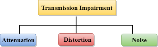
o Attenuation: Attenuation means the loss of energy, i.e., the strength of the signal decreases with increasing the distance which causes the loss of energy.
o Distortion: Distortion occurs when there is a change in the shape of the signal. This type of distortion is examined from different signals having different frequencies. Each frequency component has its own propagation speed, so they reach at a different time which leads to the delay distortion.
o Noise: When data is travelled over a transmission medium, some unwanted signal is added to it which creates the noise.
Classification Of Transmission Media:

o Guided Media
o It is defined as the physical medium through which the signals are transmitted. It is also known as Bounded media.
o Types Of Guided media:
o Twisted pair:
o Twisted pair is a physical media made up of a pair of cables twisted with each other. A twisted pair cable is cheap as compared to other transmission media. Installation of the twisted pair cable is easy, and it is a lightweight cable. The frequency range for twisted pair cable is from 0 to 3.5KHz.
o A twisted pair consists of two insulated copper wires arranged in a regular spiral pattern.
The degree of reduction in noise interference is determined by the number of turns per foot. Increasing the number of turns per foot decreases noise interference.

Types of Twisted pair:

Unshielded Twisted Pair:
An unshielded twisted pair is widely used in telecommunication. Following are the categories of the unshielded twisted pair cable:
o Category 1: Category 1 is used for telephone lines that have low-speed data.
o Category 2: It can support upto 4Mbps.
o Category 3: It can support upto 16Mbps.
o Category 4: It can support upto 20Mbps. Therefore, it can be used for long-distance communication.
o Category 5: It can support upto 200Mbps.
Advantages Of Unshielded Twisted Pair:
o It is cheap.
o Installation of the unshielded twisted pair is easy.
o It can be used for high-speed LAN.
Disadvantage:
o This cable can only be used for shorter distances because of attenuation.
Shielded Twisted Pair
A shielded twisted pair is a cable that contains the mesh surrounding the wire that allows the higher transmission rate.
Characteristics Of Shielded Twisted Pair:
o The cost of the shielded twisted pair cable is not very high and not very low.
o An installation of STP is easy.
o It has higher capacity as compared to unshielded twisted pair cable.
o It has a higher attenuation.
o It is shielded that provides the higher data transmission rate.
Disadvantages
o It is more expensive as compared to UTP and coaxial cable.
o It has a higher attenuation rate.
Coaxial Cable
o Coaxial cable is very commonly used transmission media, for example, TV wire is usually a coaxial cable.
o The name of the cable is coaxial as it contains two conductors parallel to each other.
o It has a higher frequency as compared to Twisted pair cable.
o The inner conductor of the coaxial cable is made up of copper, and the outer conductor is made up of copper mesh. The middle core is made up of non-conductive cover that separates the inner conductor from the outer conductor.
o The middle core is responsible for the data transferring whereas the copper mesh prevents from the EMI(Electromagnetic interference).

Coaxial cable is of two types:
1. Baseband transmission: It is defined as the process of transmitting a single signal at high speed.
2. Broadband transmission: It is defined as the process of transmitting multiple signals simultaneously.
Advantages Of Coaxial cable:
o The data can be transmitted at high speed.
o It has better shielding as compared to twisted pair cable.
o It provides higher bandwidth.
Disadvantages Of Coaxial cable:
o It is more expensive as compared to twisted pair cable.
o If any fault occurs in the cable causes the failure in the entire network.
Fibre Optic
o Fibre optic cable is a cable that uses electrical signals for communication.
o Fibre optic is a cable that holds the optical fibres coated in plastic that are used to send the data by pulses of light.
o The plastic coating protects the optical fibres from heat, cold, electromagnetic interference from other types of wiring.
o Fibre optics provide faster data transmission than copper wires.
Diagrammatic representation of fibre optic cable:

Basic elements of Fibre optic cable:
o Core: The optical fibre consists of a narrow strand of glass or plastic known as a core. A core is a light transmission area of the fibre. The more the area of the core, the more light will be transmitted into the fibre.
o Cladding: The concentric layer of glass is known as cladding. The main functionality of the cladding is to provide the lower refractive index at the core interface as to cause the reflection within the core so that the light waves are transmitted through the fibre.
o Jacket: The protective coating consisting of plastic is known as a jacket. The main purpose of a jacket is to preserve the fibre strength, absorb shock and extra fibre protection.
Following are the advantages of fibre optic cable over copper:
o Greater Bandwidth: The fibre optic cable provides more bandwidth as compared copper. Therefore, the fibre optic carries more data as compared to copper cable.
o Faster speed: Fibre optic cable carries the data in the form of light. This allows the fibre optic cable to carry the signals at a higher speed.
o Longer distances: The fibre optic cable carries the data at a longer distance as compared to copper cable.
o Better reliability: The fibre optic cable is more reliable than the copper cable as it is immune to any temperature changes while it can cause obstruct in the connectivity of copper cable.
o Thinner and Sturdier: Fibre optic cable is thinner and lighter in weight so it can withstand more pull pressure than copper cable.
UnGuided Transmission
o An unguided transmission transmits the electromagnetic waves without using any physical medium. Therefore it is also known as wireless transmission.
o In unguided media, air is the media through which the electromagnetic energy can flow easily.
Unguided transmission is broadly classified into three categories:
Radio waves
o Radio waves are the electromagnetic waves that are transmitted in all the directions of free space.
o Radio waves are omnidirectional, i.e., the signals are propagated in all the directions.
o The range in frequencies of radio waves is from 3Khz to 1 khz.
o In the case of radio waves, the sending and receiving antenna are not aligned, i.e., the wave sent by the sending antenna can be received by any receiving antenna.
o An example of the radio wave is FM radio.

Applications Of Radio waves:
o A Radio wave is useful for multicasting when there is one sender and many receivers.
o An FM radio, television, cordless phones are examples of a radio wave.
Advantages Of Radio transmission:
o Radio transmission is mainly used for wide area networks and mobile cellular phones.
o Radio waves cover a large area, and they can penetrate the walls.
o Radio transmission provides a higher transmission rate.
Microwaves
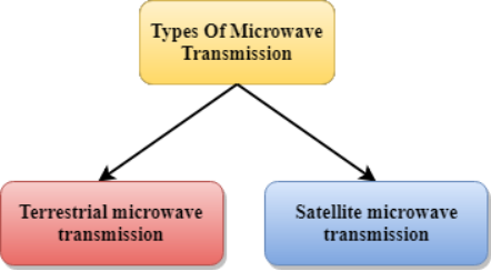
Microwaves are of two types:
o Terrestrial microwave
o Satellite microwave communication.
Terrestrial Microwave Transmission
o Terrestrial Microwave transmission is a technology that transmits the focused beam of a radio signal from one ground-based microwave transmission antenna to another.
o Microwaves are the electromagnetic waves having the frequency in the range from 1GHz to 1000 GHz.
o Microwaves are unidirectional as the sending and receiving antenna is to be aligned, i.e., the waves sent by the sending antenna are narrowly focussed.
o In this case, antennas are mounted on the towers to send a beam to another antenna which is km away.
o It works on the line of sight transmission, i.e., the antennas mounted on the towers are the direct sight of each other.
Characteristics of Microwave:
o Frequency range: The frequency range of terrestrial microwave is from 4-6 GHz to 21-23 GHz.
o Bandwidth: It supports the bandwidth from 1 to 10 Mbps.
o Short distance: It is inexpensive for short distance.
o Long distance: It is expensive as it requires a higher tower for a longer distance.
o Attenuation: Attenuation means loss of signal. It is affected by environmental conditions and antenna size.
Advantages Of Microwave:
o Microwave transmission is cheaper than using cables.
o It is free from land acquisition as it does not require any land for the installation of cables.
o Microwave transmission provides an easy communication in terrains as the installation of cable in terrain is quite a difficult task.
o Communication over oceans can be achieved by using microwave transmission.
Disadvantages of Microwave transmission:
o Eavesdropping: An eavesdropping creates insecure communication. Any malicious user can catch the signal in the air by using its own antenna.
o Out of phase signal: A signal can be moved out of phase by using microwave transmission.
o Susceptible to weather condition: A microwave transmission is susceptible to weather condition. This means that any environmental change such as rain, wind can distort the signal.
o Bandwidth limited: Allocation of bandwidth is limited in the case of microwave transmission.
Satellite Microwave Communication
o A satellite is a physical object that revolves around the earth at a known height.
o Satellite communication is more reliable nowadays as it offers more flexibility than cable and fibre optic systems.
o We can communicate with any point on the globe by using satellite communication.
How Does Satellite work?
The satellite accepts the signal that is transmitted from the earth station, and it amplifies the signal. The amplified signal is retransmitted to another earth station.
Advantages Of Satellite Microwave Communication:
o The coverage area of a satellite microwave is more than the terrestrial microwave.
o The transmission cost of the satellite is independent of the distance from the centre of the coverage area.
o Satellite communication is used in mobile and wireless communication applications.
o It is easy to install.
o It is used in a wide variety of applications such as weather forecasting, radio/TV signal broadcasting, mobile communication, etc.
Disadvantages Of Satellite Microwave Communication:
o Satellite designing and development requires more time and higher cost.
o The Satellite needs to be monitored and controlled on regular periods so that it remains in orbit.
o The life of the satellite is about 12-15 years. Due to this reason, another launch of the satellite has to be planned before it becomes non-functional.
Infrared
o An infrared transmission is a wireless technology used for communication over short ranges.
o The frequency of the infrared in the range from 300 GHz to 400 THz.
o It is used for short-range communication such as data transfer between two cell phones, TV remote operation, data transfer between a computer and cell phone resides in the same closed area.
Characteristics Of Infrared:
o It supports high bandwidth, and hence the data rate will be very high.
o Infrared waves cannot penetrate the walls. Therefore, the infrared communication in one room cannot be interrupted by the nearby rooms.
o An infrared communication provides better security with minimum interference.
o Infrared communication is unreliable outside the building because the sun rays will interfere with the infrared waves.
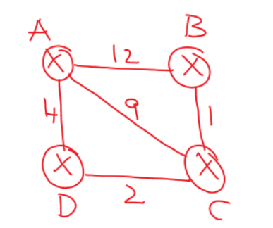
Comments
Post a Comment